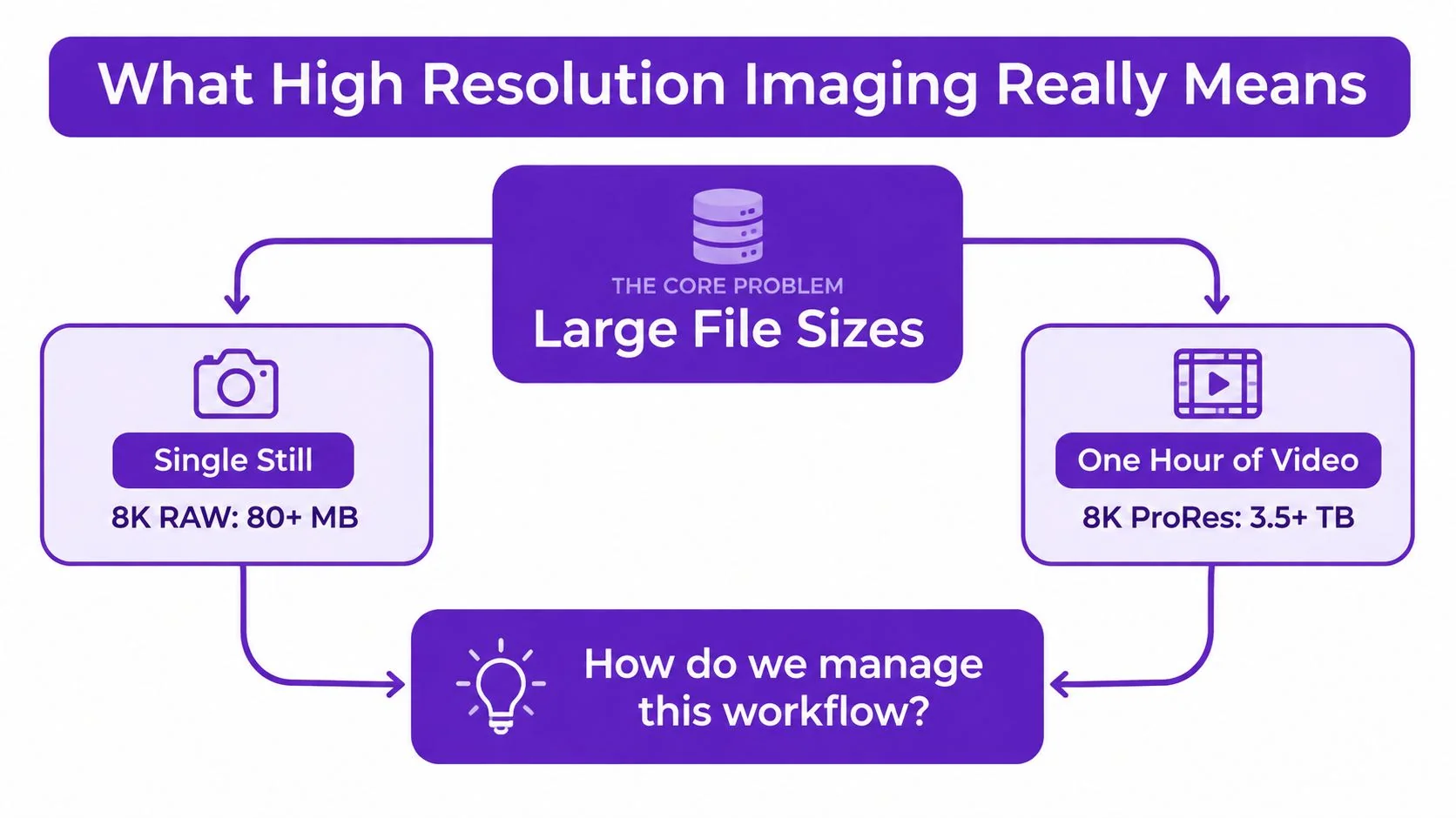
A single 8K RAW still can exceed 80 MB, while an hour of 8K ProRes footage can pass 3.5 TB. Those figures reframe high resolution imaging as more than a race for pixels. The useful question is whether your team can capture, store, process, review, transmit, and deliver the additional detail without slowing the work that depends on it.
High resolution imaging describes systems that distinguish small, closely spaced features and reproduce them with enough fidelity for cropping, enlargement, measurement, or analysis. A mosaic offers a useful analogy. More tiles can create a larger image, while smaller tiles can reveal finer patterns in the same area. Neither helps if the tiles are poorly placed, the lighting is weak, or the finished mosaic is compressed before anyone can inspect it.
The right resolution therefore depends on the entire workflow. The sections below connect the measurements, hardware paths, computational recovery methods, file formats, and operational trade-offs that determine whether extra detail creates value or just creates heavier files and slower decisions.
What High Resolution Imaging Really Means
A single 8K RAW still can exceed 80 MB, and an hour of 8K ProRes footage can pass 3.5 TB. Those figures make resolution a workflow decision, not just a contest for more pixels. The useful question is whether a team can capture, store, process, review, transmit, and deliver the added detail without slowing the work that depends on it.
A camera or microscope may record many pixels while failing to separate fine features. Resolution describes whether the full system can distinguish neighboring structures, retain their contrast, and deliver that information to the person or algorithm interpreting the image. Pixel count is only one part of the chain. Lens quality, focus, motion, illumination, sensor design, compression, and display size all affect usable detail.
A mosaic makes the relationship easier to see. More tiles can enlarge the finished picture, while smaller tiles can reveal finer patterns across the same area. Neither helps if the tiles are misplaced, the lighting is poor, or compression damages the mosaic before inspection. High resolution therefore has a capture cost, a storage cost, and a delivery cost.
Conventional fluorescence microscopy shows why the distinction matters. It is limited to about 250 nm laterally and 500 nm axially, so researchers developed methods that reveal structures standard light microscopes cannot separate, as described in this historical review of super-resolution microscopy. 4pi, structured illumination microscopy, single-molecule localization, and STED improve practical resolution through different optical or computational routes. Sample preparation can change the result too. Iterative expansion imaging demonstrated roughly 60 nm resolution, followed by about 25 nm after a second expansion step. The microscope is only one part of the measurement system.
Separate capture detail from usable detail
A practical assessment asks four questions:
- Can the optics resolve it? A sensor may sample a pattern that the lens has already blurred.
- Can the sensor record it? Pixel size, photosite efficiency, noise, and exposure determine whether fine contrast survives.
- Can software interpret it accurately? Upscaling can sharpen an image’s appearance, but it cannot restore information that never reached the sensor.
- Can the workflow handle it? Large files require storage, bandwidth, processing capacity, backups, and review time.
Medical imaging shows the field’s expanding research focus. A bibliometric study identified 3,262 medical imaging super-resolution publications from 2000 to 2023, with annual output rising from 13 papers in 2000 to 366 in 2023. (Medical imaging publication analysis)
Practical rule: Treat resolution as a budget. More spatial detail spends resources on optics, light, compute, storage, transmission, interpretation, or compliance.
The right allocation depends on the application. A pathology researcher may prioritize cellular structures that can be separated. A support team recording software may need crisp interface text at the target display resolution. A mapping organization may value ground detail only when analysts can receive and process the imagery quickly enough to act on it.
The Core Metrics That Define Resolution
Four metrics prevent most resolution discussions from becoming vague: pixel pitch, PPI or DPI, spatial resolution, and signal-to-noise ratio. They measure different parts of the image chain, so one can improve while another gets worse.
Pixel pitch and sampling
Pixel pitch is the physical distance from one photosite center to the next, usually expressed in micrometers. Smaller photosites sample more points across the same image area, but each photosite collects fewer photons unless the sensor and exposure compensate. That can increase noise and weaken fine tonal distinctions.
Digital spatial resolution is tied to pixel count and pixel size. More pixels across the same area can reduce the smallest object size a sensor can detect or distinguish, but only when the optics, focus, and lighting support that sampling. (Spatial resolution fundamentals)
PPI and DPI answer different questions
PPI, or pixels per inch, describes image pixels placed across a display or print dimension. DPI, or dots per inch, usually describes the physical dots produced by a printer. For a concrete calculation, a 300 PPI image intended for a 16 by 20 inch print requires 4800 by 6000 pixels. That requirement describes output density, not whether the camera captured sharp detail.
For screen or video work, the destination display and playback format matter more than a print DPI setting. A practical guide to optimizing video resolution can help teams align frame dimensions with how viewers will watch the material.
Spatial resolution and contrast
Spatial resolution describes the smallest distance between features that the system can distinguish. Clinical radiography often uses line pairs per millimeter as a practical test. A digital radiograph can use a 2000 × 2500 matrix. With a 35 × 43 cm cassette, that corresponds to 175 μm pixels and limiting resolution of about 3 line pairs per millimeter. A 20 × 24 cm cassette with 100 μm pixels improves limiting resolution to about 5 line pairs per millimeter. (Clinical X-ray resolution reference)
Optical systems also face diffraction. A commonly used Rayleigh relationship is approximately 1.22 times wavelength times f-number divided by aperture. The exact result depends on the system, but the practical lesson is simple. Smaller pixels can’t force a lens to reproduce detail that diffraction has blurred.
SNR completes the picture
Signal-to-noise ratio, often expressed in decibels, determines whether resolved detail remains visible. A fine edge with weak contrast may disappear into noise even when the sensor samples it adequately. As a rule of thumb, each 6 dB drop roughly halves usable tonal range, so a high-pixel image with poor SNR may contain less actionable information than a lower-resolution, cleaner capture.
| Metric | Unit | Typical range | What it controls |
|---|---|---|---|
| Pixel pitch | Micrometers | Sensor-dependent | Sampling density and photon collection |
| PPI or DPI | Pixels or dots per inch | Output-dependent | Display or print density |
| Spatial resolution | Line pairs per millimeter or distance | Modality-dependent | Smallest distinguishable feature |
| SNR | Decibels | Exposure and sensor-dependent | Visibility of fine contrast |
Think of these values as one combined budget. Sampling sets the grid, optics set the sharpness ceiling, output density sets how detail appears, and SNR determines whether anyone can trust what they see.
How Hardware Pushes the Resolution Ceiling
Hardware reaches higher resolution through different paths, and each path solves a different limitation. A sharper lens, a denser sensor, a higher numerical aperture, and a finer remote-sensing ground sample distance aren’t interchangeable upgrades.
Optics and modern sensors
A high-quality lens preserves contrast at fine detail frequencies. Fast lenses commonly use f-numbers between 1.4 and 4, but a lower f-number doesn’t automatically mean higher resolving power. Diffraction still imposes a limit related to wavelength and f-number, so shrinking pixels below the lens’s useful detail limit can produce larger files without more real information.
Modern sensors use designs such as stacked back-side illumination and global shutters to improve readout, sensitivity, or motion handling. High-resolution sensors may sit in the 24 to 100 megapixel class, while pixel pitch can range from about 0.6 micrometers in phones to 3.4 micrometers in full-frame sensors. Smaller pitch increases sampling density, but noise control and quantum efficiency determine whether that sampling remains useful.
Good lighting is part of this hardware equation, not an afterthought. For production teams, this guide to mastering lighting for video recording provides practical context for controlling shadows, reflections, and exposure before software has to repair them.
Microscopy and remote sensing
Microscopy takes a different route. Oil immersion objectives can reach 1.4 numerical aperture, and 405 nm excitation supports fine-scale fluorescence work. Deconvolution can improve apparent separation beyond the roughly 200 nm Abbe limit, but it depends on a measured or modeled blur function and can amplify noise when the input is weak.
Remote sensing shifts the measurement from the sensor to the ground. Push-broom cameras build an image line by line, while synthetic aperture radar uses motion and signal processing to create detailed measurements in conditions where optical imaging may struggle. A 0.3 to 0.5 meter ground sample distance can drive downstream mapping, classification, and inspection decisions.
| Hardware path | Strength | Main limitation |
|---|---|---|
| Precision optics | Preserves fine contrast | Diffraction, focus, cost |
| Dense sensors | Captures more samples | Noise, heat, data volume |
| High-NA microscopy | Separates small structures | Illumination, preparation, photodamage |
| Remote sensing | Measures broad areas at fine ground scale | Downlink, motion, processing, coverage |
Each path forces a trade-off. More sensor data raises storage and transfer requirements. High numerical aperture narrows working conditions. Remote sensing adds motion and acquisition constraints. The best system is the one whose detail survives the complete workflow.
How Software Recovers Detail Past the Sensor
Software can improve an image, but it can’t change what the sensor physically recorded. That distinction matters because an algorithm may create a convincing edge or texture based on learned patterns rather than direct evidence.
Single-image and multi-frame approaches
Single-image super-resolution methods such as SRCNN, ESRGAN, and diffusion-based upscalers infer a larger image from one input. They use learned priors about edges, faces, text, fabric, or natural scenes. The result can look more detailed, but texture that wasn’t captured may be plausible invention rather than recovered information.
Multi-frame super-resolution has a stronger physical basis when the source frames contain useful sub-pixel shifts. A model can align and combine those exposures, allowing information from different samples to contribute to the output. The method becomes fragile when motion, rolling-shutter distortion, exposure changes, or misalignment enter the sequence.
Deconvolution addresses another problem. Instead of inventing texture, it attempts to reverse a known blur introduced by the optics or imaging process. Bicubic and Lanczos interpolation resample existing pixels. They can produce smooth or sharp-looking edges, but they don’t create measured detail.
A useful test compares a 12 MP image upscaled 2x by ESRGAN with an image captured natively at 24 MP. The ESRGAN output may appear sharper at a glance, especially on edges, yet measurable modulation transfer function, or MTF, can still show that the native 24 MP capture preserves different contrast behavior. The two files may have similar dimensions after processing, but they don’t carry equivalent evidence.
For a practical guide to enlarging footage while maintaining readable composition, see how to zoom in a video. For still images, a tool such as the ClipNova image enhancement tool can be useful for testing an upscale, provided you compare the result against the original rather than treating generated texture as proof.
Super-resolution methods compared
| Method | Input frames | Real new detail | Speed | Best use case |
|---|---|---|---|---|
| Bicubic or Lanczos | One | No | Fast | Routine resizing |
| SRCNN-style model | One | Usually inferred | Moderate | Controlled enhancement |
| ESRGAN | One | Usually inferred | Moderate to slow | Texture and edge enhancement |
| Diffusion upscaler | One | Inferred with strong priors | Slow | Creative or presentation output |
| Multi-frame super-resolution | Several | Potentially, from sub-pixel shifts | Variable | Stable scenes and repeated captures |
| Deconvolution | One or more | Recovered from modeled blur | Variable | Known optical blur |
Watch for ringing around text, invented fabric texture, and aliasing that resembles genuine detail. In scientific, medical, or evidentiary workflows, retain the original and label generated outputs clearly.
File Formats and Workflows That Preserve Quality
Format choice should follow the image through its entire life, from sensor readout to archive to delivery. A save dialog is only one moment in that chain. The preservation question is whether you can return to the source, revise processing decisions, and produce a new derivative without compounding damage.
Build a preservation pipeline
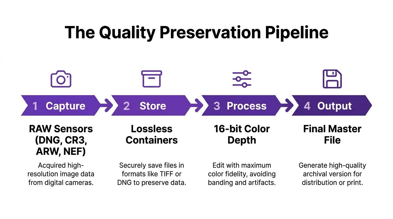
Start with the camera’s raw data. DNG, CR3, ARW, and NEF preserve sensor information in containers that defer many processing decisions. Keep these files as the source archive, with metadata and a verified backup strategy.
Use 16-bit TIFF for an archival or working master when the source and software support it. More tonal precision helps protect gradients during exposure, color, and local-contrast adjustments. An 8-bit JPEG is efficient for delivery, but repeated editing and strong tonal manipulation can reveal banding in smooth skies, skin, or studio backgrounds. PNG is useful when transparency or lossless web graphics matter, while WebP and AVIF can reduce web payloads when browser and platform support are acceptable.
A reliable sequence looks like this:
- Capture: Record RAW when future editing flexibility matters.
- Store: Preserve the original in a lossless or camera-native container.
- Process: Calibrate color, exposure, lens corrections, and sharpening in a high-bit-depth workspace.
- Output: Export a derivative for the destination, keeping the master unchanged.
Lock the right setting at the right stage
Set 300 DPI when preparing a 1:1 print workflow that requires that output density. Use sRGB for general screen delivery. Adobe RGB or ProPhoto can fit print-oriented pipelines when the full color-managed chain supports them. For JPEG delivery, quality 90 to 95 is a sensible ceiling when you need strong visual quality without treating the file as a master.
HEIC can suit supported mobile and ecosystem workflows. JPEG XL may make sense where the receiving platform supports it and smaller files justify the compatibility trade-off. TIFF-EP belongs in specialized imaging environments that need a standardized TIFF-based exchange format.
For moving images, codec choice changes whether captured detail survives delivery. A practical video codec converter guide can help teams match the source, editing intermediate, and playback file to the destination. The key principle is simple: don’t use a heavily compressed delivery file as your only editable source.
Teams producing tutorials or software documentation should also understand what a video codec is and why it matters for creators. Resolution, bit depth, color space, and compression work together. A large frame with aggressive compression may preserve less useful information than a smaller, clean master.
When Higher Resolution Creates More Problems Than Value
More detail helps only when someone or something can use it. In practice, higher resolution can increase storage, bandwidth, review time, privacy exposure, and regulatory burden while the decision benefit flattens beyond a domain-specific threshold.
Medical imaging
A 1024-slice CT scan can produce 5+ GB per study, and diagnostic reads rarely benefit beyond 0.3 mm slice spacing, according to the supplied medical workflow example. Those figures describe a real planning tension. If a department archives every possible detail without a clear clinical use, storage costs can crowd out analysis tools, faster retrieval, or governance work.
The right question isn’t whether the scanner can produce finer slices. It’s whether the additional information changes diagnosis, treatment planning, triage, or follow-up. Photon-counting CT is attracting attention because it can combine higher resolution with lower radiation dose, but clinical value still depends on interpretation, integration, and reliable data handling. (Recent medical imaging review)
Earth observation
Earth-observation teams face a similar trade-off. Pushing satellite imagery past 30 cm ground sample distance can trigger ITAR and export-control restrictions, longer downlink windows, and heavier per-scene processing. Those costs matter when the task is time-sensitive, such as flood mapping, where delayed delivery can reduce operational value.
Coverage can also be incomplete. Copernicus reported a very high-resolution European collection reaching 99.25% coverage after gap-filling acquisitions in 2025, while another update said about 10% initially remained uncovered before later completion. (Photonics and imaging infrastructure coverage)
If downstream users can’t act on the extra detail, the extra detail is overhead.
Apply that rule to every project. Ask who needs the detail, what decision it supports, how long delivery can take, and which access controls apply. High resolution imaging should reduce uncertainty, not bury a usable answer beneath files no one can move or interpret in time.
Practical Best Practices and Common Pitfalls
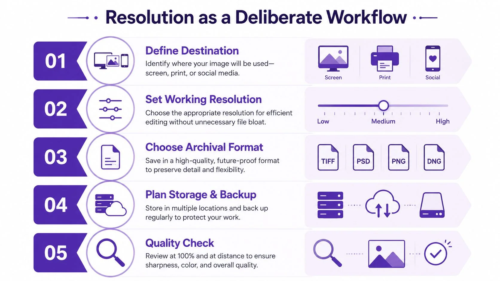
Treat resolution as a set of deliberate workflow choices. Start with the destination, then work backward to capture settings, working files, export rules, and quality checks.
Make the destination explicit
Define whether the result is for a screen recording, full-frame video, social media, print, microscopy, or a large-format display. For screen recordings, export at the target display resolution, such as 1920×1080 or 3840×2160, use full-range RGB where the workflow supports it, select a widely supported profile such as Rec.709, and avoid unnecessary post-export scaling.
Dense interfaces and scrolling content need visual pacing as well as pixels. Use smart zooms to reveal small controls without hiding essential context. Crop the smallest useful area, animate the zoom briefly, and preserve a clean, high-bit-rate source before editing.
Preserve evidence before enhancement
Keep the original capture and an uncompressed or losslessly compressed master. Apply destructive edits only to derivatives. This protects you when a client needs a different crop, a reviewer questions an enhancement, or a team must prove what the source contained.
Common mistakes include:
- Confusing resolution with focus: More pixels won’t repair a soft lens or missed focus.
- Mistaking PPI for captured detail: Changing a print metadata value doesn’t add sensor information.
- Sharpening too aggressively: Halos can make edges look artificial and obscure the true boundary.
- Calling interpolation recovery: Resampling changes dimensions, not the evidence in the original.
- Removing metadata casually: Provenance, capture settings, and timestamps may support auditability.
- Using enhancement to hide defects: AI processing shouldn’t conceal noise, motion blur, poor exposure, or uncertain interpretation.
Validate the delivered asset
In medical, security, remote-sensing, and other sensitive contexts, use access controls, encryption, approved retention rules, and visible provenance. Never upload confidential or regulated material to an unapproved service.
Finish at 100% zoom. Inspect edges, fine text, repeated patterns, gradients, and motion areas. Compare the result with the intended display, then record the capture settings, export settings, color profile, processing steps, and privacy decisions used. That record turns a one-off high resolution imaging job into a repeatable workflow.
Tutorial AI turns a single screen recording and spoken narration into a polished tutorial video that looks edited in Adobe Premiere Pro, then generates a matching written article from the same recording. Visit Tutorial AI to create product demos, onboarding videos, help-center articles, internal training, and sales walkthroughs while preserving a clear, reviewable source workflow.